4.1 THE CONSTRUCTION OF A BISAYAN HARP
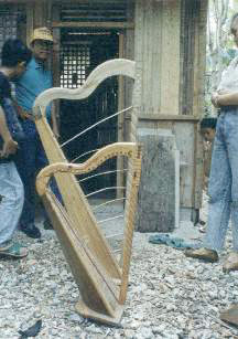
The Bisayan harp outlined in this chapter does not conform structurally to most others of its genre in that it has a staved resonator box instead of one made from a hollowed log. This is, however, another example of diversity seen within the genre.
The criteria used for selecting a harp maker to study was based primarily upon the availability and honesty of my informant. There was another harp maker found previously in Cebu who could have filled the harp making requirements of this field research; he made the hollowed log harp I purchased in 1990. Unfortunately, this man was not situated in one particular place for any length of time and demands for money were uncertain.
I was very lucky to find a good informant on the island of Bohol and to have the opportunity of documenting the entire harp making process, especially since this craft is so rare in the Visayas. In addition, the circumstances for field research were convenient and my informant was extremely helpful. Once the price was set there never was any added bidding for further compensation.
Finding my informant came about when a friend asked his cousin, a school teacher, to inquire about harps and harp makers in her hometown of Tagbilaran, Bohol. Fortunately, she asked students in her elementary music class and found one student who actually knew a man who made harps. Together, we all contacted this harp maker one day and set up a later time when I could come for an extended stay in Bohol to document the harp construction.
4.2 LOCATION OF HARP FABRICATION
Described in this chapter is the basic process of harp construction completed during a one month period from November 7 to December 8 of 1991 at the Lagtangon residence of Cornelio Abecia on the Central Bisayan island of Bohol. Lagtangon is a barangay approximately 2 km from the municipality of Maribojoc and 15 km north of the Bohol provincial capital, Tagbilaran City. Maribojoc was one of the earliest Jesuit settlements on Bohol and in the Visayas, founded in the first decade of the 17th century. Lagtangon is located directly on the national highway circling the island. Although it is a rural and agricultural area, Lagtangon is easily accessible from Tagbilaran City by public transportation, (i.e. buses and jeepneys).
It is rare to find a harp maker in the Visayas at all, and especially one who manufactures harps professionally. Most Bisayan harps encountered during this research were either made by the players themselves or handed down through relatives or friends. Many of the older Bisayan harps examined during the research period had no known history.
Mr. Abecia was born 31 March 1919 on Bohol. He can be viewed as a semi-professional harp maker because harp construction was never his primary endeavor; boat building and house construction constituted most of his livelihood. Carpentry is a common skill for many men in the Philippines and was the usual trade of those few harp maker/players interviewed. This was also true for Abecia. He had made more than twenty harps over, roughly, thirty-five years. He welcomed the work of building this specially contracted harp, as he lived alone and received little cash as a rule. Mr. Abecia graciously allowed the intrusion of documentation and was very proud of his harp making skills, wanting a record kept for posterity. None of his friends, neighbors or relatives seemed interested in perpetuating the harp building tradition in the area even though he encouraged it and was willing to teach the trade for free. In addition to building harps and other stringed instruments, Abecia played the guitar and harp to entertain himself and friends. He gave harp lessons to those interested or who bought a harp. He spoke Bisayan and Spanish, very little English, and was not formally educated past elementary level. He lived on his family's ancestral land situated next to the mangrove forested ocean front about one hundred meters from the national highway. This was also the location of the harp's construction.
Abecia initially used a neighbor's antique harp as a model for his own version; he made his first harp shortly after the end of World War II. The original harp used as a model was destroyed over the years.
Abecia's harps do not differ proportionally from each other, though different neck/forepillar joints and carved motifs may vary to accommodate his personal tastes or a particular request by a customer. He built two primary harp sizes, regular and small (gamay). (see Figs. 3.1, 4.24) It is the construction of the larger model that is described in this chapter.
Abecia's harps are all made with staved resonator boxes versus the more dominant hollowed body harps described in the last chapter. He believed that hollowed body harps were crude and that staved harps were the best. His ideas were divergent from the majority but still consistent with the assertion of Bisayan individuality in harp making.
Only hand tools were used for the construction of this harp. No electricity or power tools of any kind were available at his home. While each harp Abecia made presented different problems in construction, the essential construction techniques he developed evolved through his past experience of making harps. Abecia knew what the basic dimensions would be for the entire harp based upon the height of the forepillar. If the forepillar were a greater length, then other dimensions of the harp would expand proportionately. The small model harp did not correspond exactly to the proportions of the larger one. Abecia usually made harps by himself, but because of the unusual situation this research brought to bear, a neighbor friend named Gabing was asked to help with manual labor.
When contracting the harp, an agreement was made that all aspects of the fabrication process were to be in the presence of the researcher for documentation. Most important aspects of fabrication were either photographed, video taped or written down.
4.4.1 Four Basic Structural Units
In this chapter, as in the last, the Filipino harp is separated into four general structural units, the resonator box, the forepillar, the neck and the base. Each unit in construction is described individually. Since each general structural unit involved uses different materials and applications of construction, this approach seems the best way to organize the overall description. This system of organization is not a step-by-step portrayal; a day-by-day chronology of construction is shown in the work schedule in the appendix.
All wood materials used for harp construction were previously dried and aged. Wood that was dried for at least ten years was considered the best for making harps by Abecia. Most of the lumber used in this harp was salvaged from abandoned houses or other buildings which were over seventy years old. Material in this aged state has already gone through shrinking, twisting, splitting, or cracking and was not likely to change drastically after being assembled into an instrument. No trees were cut specifically for this harp.
As geography changes so does the material culture. This is true in the Philippines with each island showing variations in material culture as well as differences in economic stratification. This allows certain people access to materials that others may not have. So, it is common in the Philippines for people to use what is on hand. Filipinos are known for using whatever materials or adapting whatever tools are necessary to get a job done. The manufacture of this harp can be seen as an example of this ingenuity.
Fortunately, the Philippines is tropical and many species of plant life exist. Even though forests are being denuded much too rapidly, there is still a diversity of material to choose from, at least in small quantities.
For this harp, Abecia decided to use different kinds of wood for variety, beauty, and strength; nangka for the resonator box and edge moldings; tugas (molave) for the forepillar, lumbayau for the base, robles for the neck and foundation block, hindang for the soundboard and sibucao for the pegs and wooden nails. Each kind of wood is described for each structural unit.
Only common carpenter's hand tools were used to build the harp. A list is given below with vernacular names available.
Three different planes or sapilla; a narrow plane used for leveling the sides, a medium sized plane, and a longer plane.
Bolos - long knives, similar to a machete, approximately 14-18 inches in length and 2-3 inches in width.
Saws- Two kinds of wood saws, one smaller than the other.
Awl- Similar to an ice pick, a sharply pointed, thin metal rod with a wooden handle.
Chisels- different sizes of chisels were used, 1/8 to 1 inches in width.
Sand paper
Scraper- this tool was pushed forward away from the body to cut small slices of wood
Metal compass
Brace and bit- type of drill used for peg holes
Chalk line and reel- used to snap visible lines onto the wood
Folding ruler- wooden ruler (in inches)
Marking gauges- two kinds, used to score guide lines for sawing and cutting
Rope- used to hold together joints of assembled harp
Hammer- regular carpenter's hammer
File- to sharpen saws
As described in the previous chapter, the resonator box unit is a multi-component structure of various constituents. For this harp, components included, the foundation block, 5 staves, the soundboard, 2 edge moldings, and 1 center strip. (see Fig. 4.19) The base is not included even though some might view it as part of the resonator box unit.
4.5.1 Foundation Block/pundasyon
4.5.1.1 Type of Wood Used for Foundation Block
A wood called "robles" by Abecia, was used for the both the harp's foundation block and neck. It is a wood for which the scientific name could not be identified because the vernacular name was not found in any botanical references available. Robles, in Spanish, actually translates as oak. However, this Filipino "robles" is a tropical wood and is not like a deciduous oak which loses its leaves in the Autumn. The Filipino wood called robles is of medium hardness and has an attractive curving grain pattern with a contrasting two tone color (black and white), with the darker wood being the heartwood. Robles is easily worked, though it tends to chip. Abecia also used this particular wood for the sound board on another harp. Robles, Abecia said, can be found around the municipality of Anda on the east coast of Bohol.
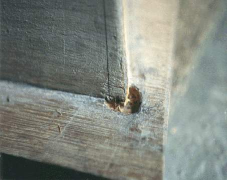
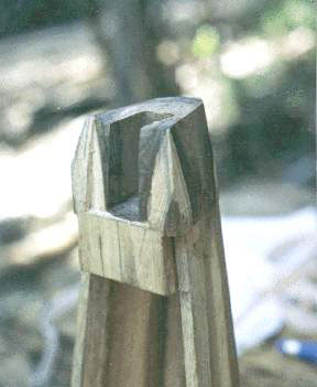
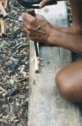
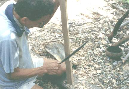
The foundation block was initially cut from a small log of robles, using a hand saw, to a length of approximately 13 cm (5 in) and a diameter of 10 cm (4 in). On this piece measurements were made with ruler and tri-square and lines were drawn on the top and sides with a pencil. Measurements for the block were based upon a predetermined size and shape known to Mr. Abecia. (see Diag. 4.1 and 4.8) From these initial measurements the first rough cuts were made using a bolo. Once the rough block was cut, an angular groove or indention was cut around the bottom edge using a hammer and chisel. (see Fig. 4.1) This cut was to facilitate the eventual attachment of the staves. Other cuts and adjustments to the foundation block were made to fit the contour of the harp depending on the progression of construction.
Eventually, a mortise was cut after the staves were attached and the neck was readied. (see Fig. 3.10) After the neck was joined to the foundation block, cuts were made with a hammer and chisel to develop a the continuity of contour seen on the finished harp. (see Fig. 4.2) Other cuts were made over a period of time to allow partial insets of the soundboard, moldings, and centerstrip. This will be described later.
4.5.2 The Staves/coverta or acob
4.5.2.1 Materials Used
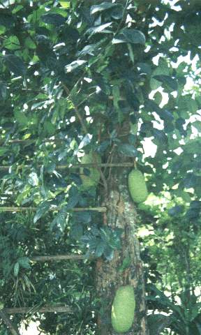
Staves of this harp were made from nangka. Nangka is a fruit bearing tree commonly called jackfruit. (see Fig. 4.3) From the very large Moraceae family (Antipolo family) which contains few important timber trees, the best known trees of this family are malambingan, antipolo, anubing and nangka. A description of nangka is given below from Plants of the Philippines.
Langka or nangka is about 12 m tall and has the reputation of bearing the largest fruit in the world. The leathery leaves show variations. Polymorphism in langka leaves occurs in the same plant, meaning that the foliage are of different types. Other examples of polymorphism may be found among many aquatic plants, in which the aerial and submerged leaves are quite distinct. Sometimes the same species may show two distinct leaf forms when grown under wet and dry conditions; that is, a tendency to develop scale like leaf forms under dry conditions and expanded broad forms under wet conditions. Sometimes, in langka, the leaves of young shoots in the same plant tend to be lobed while those of the matured shoots are oval or oblong and not lobed. Cauliflory is common in langka. The numerous small male flowers are in dense, elongated club-shaped clusters while the female flowers are produced in globular heads. The huge fruit is generally eaten raw but it may be cooked as a vegetable when unripe. The ripe fruit is made into sweets, candies, and jellies. The starchy seeds are roasted or boiled. Propagation is by seed, the plant bears fruit in 7-8 years. The wood is good for cabinets and musical instruments and also produces a yellow dye. (Asis 1971: 100, 112)
The wood from this tree is an important material for harp making in the Visayas and, like the coconut, it is a highly valued tree in Filipino society and is also well-respected throughout South-East Asia.
The wood derived from this tree is favored by Filipino instrument makers. Guitars, violins, harps, ukuleles and any other musical instrument common in the Philippines of European or Westernized ancestry are often constructed of nangka. Research on the use of nangka in pre-Hispanic Filipino instruments is not readily available. As mentioned in Chapter 3, a large percentage of harps examined in the Visayas used nangka for, at least, the resonator box. Some harps were made of nangka for virtually the entire instrument. Excerpted below, an 1842 publication describes some attributes of nangka:
Nangka, arbol de la provincia de Leyte; sirve para instrumentos musicos; elasticidad 4, resistencia 848, esta madera es vistosa y tambien la usan par escribanias. (Informe 1882:194)
Nangka, a wood from the province of Leyte, serves for musical instruments; elasticity 4, resistance 848. The wood is colorful and is used for writing as well.
Abecia described nangka as the best wood for harp construction because of its resistance to dry rot and insects. It is of medium hardness and fairly easy to work. The wood has reasonably straight grain and tends not to split. Nangka's natural yellow color is beautiful when finished. The widespread belief in the Philippines that nangka makes for better musical instrument sound quality would be difficult to prove scientifically. No acoustic testing with electronic audio equipment was done in this research.
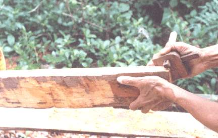
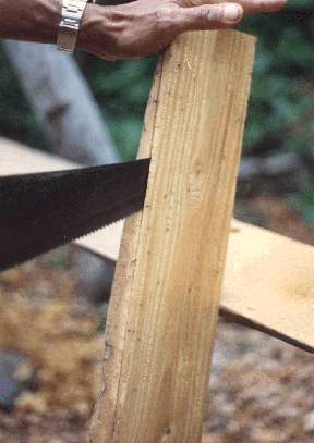
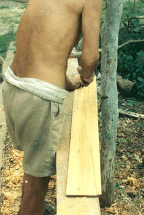
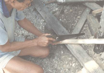
An aged length or bolt of nangka lumber approximately 110 cm (43 in ) long by 12 cm (4.5 in) wide, by 10 cm (4 in) deep, was initially planed level on one surface of its length and width. A bolo was then used to trim the side edges (depth) to make a flat surface to facilitate the use of the marking gauge. The marking gauge, set at approximately .8 cm (5/16 in), was used to score a mark around all four edges of the nangka lumber. (see Fig. 4.4) Using this mark as a guide, a rip cut was made (with the grain) with a sharpened saw. (see Fig. 4.5) A wedge was used to widen the gap between the log and the stave board as the sawing progressed. Three boards were cut from the same piece lumber in exactly the same way. Sawing one board off at a time was a slow process, with each board taking most of a day to cut. There was never a hurry.
Fig. 4.3 -- Live nangka tree with fruit
Fig. 4.4 -- Marking gauge used to obtain correct thickness for stave to be cut
Fig. 4.5 -- Cutting stave from nangka with a saw; note smoothness of facing side
Once three rectangular boards were cut it was apparent that each board had one ragged surface due to unevenness in the sawing motion. Only one side of each board was rough since the opposite surface had already been planed before it was cut. Thus, the rough surfaces on each of the three boards went through a planing procedure to make them level and of an even thickness.
With this was done, the boards needed only minor finishing to make them smooth enough for the next step of bisection. For this final finishing, the boards were wetted and planed with the plane's blade set to cut very thin shavings of wood.
Once the three boards were planed and finished, six triangular shaped boards were obtained by bisecting each of the three rectangular boards. One of these six staves was extra since only five were needed. The procedure for bisection was first to snap a chalk line across a board diagonally, and then saw it in half along that chalk line to get two triangularly shaped trapezoidal staves from each rectangular board. (see Fig. 4.6) Four of the staves were divided into two sets, the staves of the first numbered 1 and 2, and the staves of the second numbered 3 and 4 respectively, because of the order of attachment to the foundation block. The side edges (depth) of staves 1 and 2 were planed simultaneously (see Fig. 4.7) to insure the same dimensions (2 cm x 9 cm x 110 cm), as were staves 3 and 4, but with slightly different dimensions (3.5 cm x 11.5 cm x 110 cm).
Fig. 4.6 -- Bisecting nangka board in half to form two staves
Fig. 4.7 -- Planing two staves at one time to make both identical using a narrow plane
As noted before, there was an angular groove carved around the bottom portion of the foundation block to facilitate joining the staves together. The first two staves to be joined were the two nearest the center rear stave number 5. Before joining, though, minor adjustments had to be made to the angular groove in the foundation block using hammer and chisel to allow for the correct angle of alignment. (see Fig. 4.1) Adjustments were also made to the staves' ends so they would, as well, fit flush against the block.
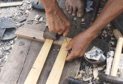
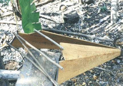
Once the adjustments were finished, staves 1 and 2 were glued and nailed to the foundation block. To accomplish this, first, three holes in a triangular pattern were punched with an awl through the narrow end on each of the two staves. (see Fig. 4.8) This was at the point of contact where the stave connects to the angular groove of the block. These pre-punched holes were done so the wood would not split when nailed. Glue was then applied to all points of contact on the foundation block and the stave ends. To obtain the correct angle of alignment, a stave was placed and nails were pounded in one at a time, Abecia checking the alignment after each nail. After the two staves were glued, aligned, and nailed, the space between the two staves on the opposite, or widest end, were measured. Sticks taken from a nearby bush were cut and adapted to use as temporarily braces. (see Fig. 4.9) These were to help set the correct angle and distance between the two staves while the glue dried. This first portion of the resonator box was then left to dry for a full day.
Fig. 4.8 -- Pre-punching nail holes
Fig. 4.9 -- Adding temporary bracing to gap the two staves apart the correct width
4.5.2.5 Joining Staves 3 and 4 to the Foundation Block and to Staves 1 and 2
Next attached were the staves closest to the soundboard, numbered 3 and 4. These also would be joined along the edges to the corresponding edges of staves 1 and 2 respectively (Stave 1 joined to stave 3 and stave 2 to stave 4). Adjustments to the stave edges of 3 and 4 were made with a plane. Little by little, the two sets of adjoining staves were made to fit flush without any discernible gap along the joint. The adjoining edges of staves 1 and 2 were left without adjustment at an 90 degree angle, while staves 3 and 4 were planed to fit the required angle of the resonator box shape.
Minor adjustments on the foundation block and staves' ends again allowed all points of contact to be at the correct angle of alignment, both on the foundation block and along the stave edges joined. Following this adjustment procedure, glue was applied to all joints of contact on the block, stave ends and stave edges where the two sets fit together. One at a time each stave was attached. Several temporary nails were then driven down the length of each stave joint to help clamp the staves tightly together. The nails were set only about halfway in down the lengths so they could be easily removed after the glue dried. No nails were left permanently in the joints between the staves. Also, temporary nails driven first through tiny blocks clamped the staves to the foundation block. These would also be taken out after the glue dried, unlike the permanent nails left in staves 1 and 2 at the foundation block. Abecia liked to use as few nails as possible in his harps, so very few were left in permanently.
After the joining of staves 3 and 4 to staves 1 and 2 respectively, more temporary braces were placed between the widest end for correct spacing and alignment. This section was left to dry for one day before the final stave number 5 was attached. (see Fig. 4.10)
The rear, center stave number 5 was not quite wide enough after bisection, so a small wedge of wood had to be added to extend the width at the bottom. This took a short time to make but a day for the glue to dry before resonator box construction could proceed. (see Fig. 4.11)
Once finished with the stave extension, Abecia cut sound box holes in stave 5 before it could be joined between staves 1 and 2 and onto the foundation block. The procedure for the cutting sound holes began by first determining the hole placement. Once the general area was determined a center point was found using a ruler and marked. With an awl, a small hole was punched all the way through the stave to the opposite side. This first little hole allowed for the compass, set at a radius for each different hole of 3.75 cm (3 in.), 2.1 cm (1 1/16 in), 1.1 cm (7/16 in.) respectively, to score an outline of the hole on one side of the stave. The stave was turned over and the compass set to the same radius was used to score the opposite side using the same center point. Next, the compass was reset at a slightly smaller radius, approximately 0.2 cm, and was used to score another outline inside the first outline on both sides of the stave. The reason for this was to first cut a thin groove all the way around the diameter of the hole on both sides of the stave using the two compass outlines as guides. (see Fig. 4.12)
Fig. 4.11 -- Addition of width extension on to stave 5
Cutting around each of the three holes in this manner eventually allowed the circular disks to pop out, making a clean opening with no splinters or exterior cracks in the wood. Three holes were cut in descending diameter up the narrowing stave. A slight bevel was made with a chisel around the edges of the three holes on what would be the inside of the resonator box.
4.5.2.8 Joining the Rear Stave to the Foundation Block and Staves 1 and 2
Before gluing the final stave, adjustments were made with a plane to both edges of stave 5 so they would fit flush to the adjoining and corresponding edges of staves 1 and 2, which were again left at a 90 degree angle (depth to the width). Adjustments were also made at the points of contact of the foundation block using a chisel to correct the fit. Once all joints were flush and without any gaps, glue was applied on all areas of contact and temporary nails were driven down the length of the joints between staves 1 and 5, 2 and 5, and into the foundation block. The same nailing procedure was done as before. This finished portion was then left to dry for a day and the temporary nails removed.
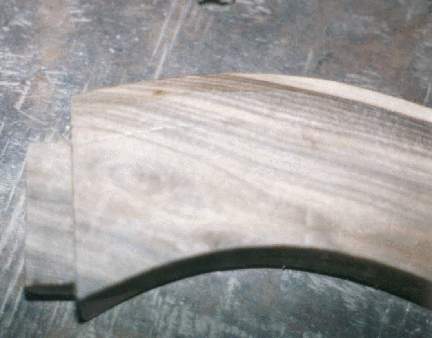
4.5.2.9 Cutting the Bottom of the Resonator Box to the Correct Angle
After this initial resonator box structure was built (minus the soundboard) a staggered edge was left on the widest end of the bottom due to the varying angles the staves took from the foundation block, which resulted in uneven lengths. To cut the staves so the resonator box would be
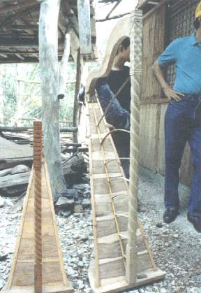
at the correct angle of tilt on the base, there was a laying out process whereby the forepillar, neck, base, and resonator box units were loosely pieced together temporarily (see work schedule in appendix for actual event sequence). (see Fig. 4.13) Using the length of the neck to judge the correct distance between the forepillar and the foundation block, an estimated angle of tilt was decided upon and the resonator box was marked accordingly. A saw was used to make the cut around the bottom of the resonator box. (see Fig. 4.14)
The soundboard was built only after the assembly of the resonator box, neck, forepillar and base units.
Hindang, the wood used for the sound board, is of the genus Litsea. The species used for the harp could be either marang [L. perrottetii], sablot malcadios [Beilschmiedia cairocan], or bangulo [L. garciae], judging by the description below.
A genus of 35 or more species, of which only a few are fairly well known. The woods are of three rather distinct types, which are represented best by sablot (L. glutinosa), baticulin (L. obtusata), and marang (L. perrottetii) the latter known as white baticulin. (Schneider 1916: 110-111)
Bangulo [L. garciae] is a tree up to 60 centimeters in diameter, reported from Laguna to S. Luzon, Mindanao, Samar, Leyte. Wood a rather coarse textured white baticulin, practically identical with marang (L. perrottetii). (Whitford 1911:32)
Abecia said that the light colored hindang used in the harp came from an old house over one hundred years old and that trees of this species could be found around Pintuyan, Leyte. He described three kinds of hindang, white, black, and yellow. Forestry references above mentioned Leyte as one of the places where the species of hindang exists. The wood is light colored, of medium hardness, fairly heavy and the grain straight and compact. Since the soundboard must be thin, properties of this particular wood were applicable to the purpose. The hindang soundboard slats were planed down to ~ 0.2-0.3 cm (1/16-1/8 in).
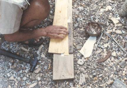
Boards or slats for the soundboard were sawed from a bolt of hindang initially 40 cm (l) x 15 cm (w) x 30 cm (d). (see Fig. 4.15) Processing of the lumber into slats was by virtually the same procedure as with the nangka
Fig. 4.15 -- Planing block of wood for soundboard slats to be cut by Gabing
stave boards, except that the soundboard slats were not bisected diagonally and were cut and planed thinner.
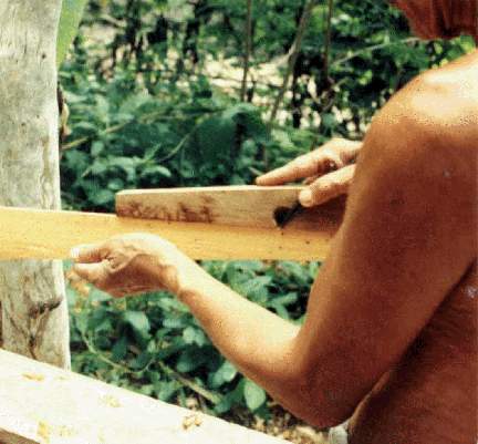
The process of laying out the soundboard started by taking the rectangular slats and placing them, one on top of the other, onto the resonator box of the mostly, assembled harp. Each segment was laid across the exposed gap, and using a pencil, the exterior outline of the resonator box was traced onto the slat, extracting the correct dimensions for each slat in ascending order. (see Fig. 4.16) With a saw, the slats were cut to fit the traced trapezoidal outline. All slats of the soundboard were joined together on a 90 degree butt joint except the lowest and widest edge of the first slat, because it had to fit the corresponding angle of tilt to the horizontal surface of the base. The procedure of outlining, sawing, planing, each individual slat continued until the whole soundboard was laid out on the standing harp.
At the top of the soundboard a small horizontal cut was made into the foundation block to allow the soundboard at that point to be set into it. This part of the foundation block would then act as a strong contact point on the upper and narrowest end of the soundboard. Once this process was finished on the harp the next step was to glue the soundboard segments together into an integrated unit.
The procedure for jointing and gluing the soundboard together began by arranging the pre-cut pieces on a flat bench. The edges were sized up
Fig. 4.16 -- Laying out of soundboard slats on resonator, penciled line to be cut for correct fit
and minor adjustments made at that time. The process of gluing the slats together was then done two boards, or, one butt joint at a time.
A moveable clamping system was devised to glue the entire board together at one time. This was done by first nailing a stationary block of wood onto the bench to hold the first, and widest slat in place by stopping its movement when the adjoining slat was pressed against it. Before gluing the pieces together, a strip of paper was placed directly on the bench under each joint so the soundboard would not stick to the bench after the glue dried. Glue was then applied to the butt edges of the two slats and joined together. To make the joint tight a temporary block was nailed into the bench opposite the stationary block on the narrower slat end, but nailed in with a slight angular gap left between the slat and the temporary block. The angular gap allowed for a triangular wedge to be tapped in between the slat and the temporary block to tighten the joint together for a pressure fit. (see Fig. 4.17) Once the two slats were tightened together using the wedge, several nails were driven half-way or temporarily through both slats and into the layout bench. Nails were placed along the width of the joint and along the outside edges of both slats lengthwise, in various places. This kept the soundboard lying down flat against the bench and kept the soundboard from bowing due to the strong pressure exerted by the tightened wedge. Since the nails were only temporarily set they could be removed once the glue dried.
After each butt joint was glued, another paper strip, similar to first, was placed over the top of the joint with an application of glue. This was to further strengthen the butt joint which in itself is fairly weak. Because the temporary nails held the boards flat and immobile and the joint tight, the temporary stop block and wedge could be removed and reset for each soundboard segment joined in the repetitive sequence.
Drying the soundboard on the bench took one day, then both stop blocks, wedge, and temporary nails were removed. The next step entailed ripping and sanding off the bottom paper strips laid down on the bench to keep the soundboard from sticking. The strips stuck to the soundboard due to the excess glue squeezed from the joint and needed to be removed as they were attached to the exterior face, the side exposed to view when on the harp. The other set of paper strips over the joints on the opposite side were left on the joints of the soundboard as these would help to strengthen it and would not be readily seen as they would be on the inside of the harp.
Before joining the soundboard to the resonator box, an additional strip of nangka wood was attached, laid width side down onto the base. The strip was used as an additional nailing and gluing surface for the soundboard and spanned inside the resonator box at the widest point on top surface of the base. The dimensions of the gluing strip were 0.5 cm (d) x 2 cm (w) x 35 cm (l).
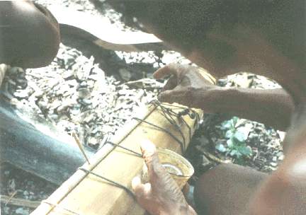
After removing the paper, and adding the extra wood strip, the soundboard was placed on the standing harp to size up the fit and to make any adjustments needed with the plane and chisel. Once the minor adjustments were made, the soundboard was attached to the resonator box. In this procedure, glue was applied around all of the contacting edges of the soundboard, the resonator box, the gluing strip, and the portion of the soundboard where it set into the foundation block. To clamp the soundboard onto the box and hold it securely while the glue dried, a rope was tied around the forepillar and then wound spirally around the box ascending from the bottom and tied on top. Some temporary nails were also driven in through the soundboard and into the outside stave edges, to add extra strength to the joint and to keep the rope from slipping loose. The harp was then left to dry for a day before the temporary nails and the rope were removed.
The next step was the addition of edge moldings. To make the edge moldings, called ribete, a rectangular length 1.9 cm (.75 in) x 3.8 cm (1.5 in) x 104.2 cm (41 in) inches was cut from a piece of nangka. This length was then cut into two equal parts and both lengths were planed down to 1.45 cm (9/16 in) x 1.8 cm (11/16 in). Once this was done, a marking gauge was used to score lines at 1.95 cm (3/8 in) on two adjacent sides of each length of nangka (see Diag. 4.2). No other edge moldings were used on this harp.
Diag. 4.2-- Dimensions of the edge molding
Exposed edges of the moldings were rounded using a plane, after the initial gouge was cut. After the moldings were cut and rounded, the next step was to attach them to the resonator box. One molding at a time was attached. The procedure for this began by notching the base at the point were the molding was to inset. (see Fig. 4.19) Also, cuts were made into the foundation block on the opposite end to allow the molding to inset there as well. (see Fig. 4.20) Just before joining the molding to the box, minor adjustments were made to correct any problems with gaps along the length. Glue was applied to all points of contact: in the groove of the molding, in the cuts made in the base and the foundation for the inlay, and on the resonator box. After this, the first molding was placed and the rope was wound around the box to hold the molding tight, similar to what was previously done to the soundboard. (see Fig. 4.21) Temporary nails, first put through tiny blocks of wood, were driven through pre-punched holes made with an awl into the molding and the forward staves of resonator box. The temporary nails were used to secure the molding and to keep the rope from slipping as before. In addition to the glued edges and temporary nails, permanent wooden nails, called pasuk, were added to make for a more solid joint.
Pasuk (~ 0.15 cm in diameter) were whittled from small splinters of sibucao (see section on tuning pegs). To insert the pasuk, holes were first pre-punched with an awl entirely through the molding and the stave wood on the box side of the harp (not the soundboard side) about every 21 to 30 cm. Pasuk were also inserted through the molding and partially into the
Fig. 4.18 -- Gouging corner out of molding strip with hammer and chisel
Fig. 4.19 -- Gouge made into base for the molding to inset
Fig. 4.20 -- Cut made into foundation block for molding to inset
After marking the molding along its length, a chisel and hammer were used to gouged out an angular groove between the marked lines. (see Fig. 4.18) The acute angle (less than 90 degrees) made on the moldings was designed to fit the edges where the soundboard joins the staves. The wider side of the molding (11/16 inch side) was fit flat against the soundboard face, while the narrower side of the molding fit flush against the staved side. foundation block about 1.2 cm (1/2 in) deep. To fit the pasuk into the pre-punched holes, a sequence of adjustments were made. The slivers of wood were whittled little by little, and alternately pushed into the holes and checked as to the fit, taken out, whittled some more, and checked again until they fit tightly all the way through the holes into the resonator box. Once this was finished, glue was applied into the holes and on the wooden nails. (see Fig. 4.22)
The pasuk were then tapped tightly into place and the excess wood sticking out was chopped off with a bolo, flush with molding. With pasuk glued in, the rope was taken off the first molding and the same procedure followed to attach the second molding on the other side; cutting the base and foundation block for the inset, applying glue, driving temporary nails, winding the rope around the box to tighten the molding to the resonator box, and then the fitting and gluing of the wooden nails. The added moldings were then left to dry for a day before the rope was taken off and the temporary nails removed.
The centerstrip, also called litson or also ribete, is a component on nearly every Filipino harp, a thin strip of wood or bamboo that is placed down the center on the exterior surface the full length of the soundboard. The centerstrip serves a dual purpose, one as an exterior soundboard brace and as a guide for the strings to be placed through the soundboard into the interior of the resonator box. It is also useful to keep the strings from cutting up into the soundboard due to the upward pressure exerted from their tensions.
The centerstrip on this harp was made from a thin strip of nangka 99 cm (l) (39 in) x 1 cm (w) (3/8 in) x 0.3 cm (d) (1/8 in). The top exposed width was rounded on the edges and the strip laid widthwise down the center of the soundboard. After the edges were rounded, a line was drawn in the middle of the centerstrip as a guide for the string hole placement. To attach the centerstrip to the harp, a chalk line was snapped down the center of the soundboard. Glue was then applied along the chalk line and on the flat contacting side of the centerstrip and joined together. After the centerstrip was placed, six thin strips of split bamboo were bowed between the forepillar and the length of the centerstrip to hold it tight as it dried. (see Fig. 4.23)
String holes were punched only after the centerstrip was added to the soundboard. Therefore, holes were made with the awl completely through both the centerstrip and the soundboard at one time. Hole sizes for the strings varied, with slightly enlarged ones at the bottom to fit the larger diameter strings. (see Fig. 4.24)
The placement of holes in the soundboard's center strip is uniform and evenly spaced 3 cm (1 3/16 in) apart. The distance between the string holes was based upon the number of strings required and the length between the placement of longest and shortest possible strings.
The base is described as a separate unit, basically because it acts as a connecting surface for both the resonator box and the forepillar.
Philippine mahogany [family of Dipterocarpaceae] is a general term referring to a number of different species with a similar material quality. Most common types are lauan, white [Parashorea malaanonan], red [Shorea negrosensis], and brown. For this harp's base a Philippine mahogany species called lumbayau [Heritera javanica] was used.
To make the base, two short planks of lumbayau 41 cm x 15 cm x 2 cm (16 in x 6 in x 3/4 in) were joined together to produce the required dimensions for the base. This material was actually pieces of flooring taken out of an old building. Since the boards were already flat, not much processing was needed. The adjoining edges of the two boards were planed so there would be a good fit at the butt joint. The joining of the two boards was done similar to the way the soundboard was built. The two base boards were placed between stop-blocks which were nailed onto another flat board. One of the stop-blocks was gapped to allow a wedge to be driven between the adjoining boards and the block. After applying the glue to both sides of the joint, the two boards were placed together and the wedge was tapped in to squeeze and clamp the boards tightly together. After the glue dried, this jig was taken apart and a plane was used to smooth any rough surfaces.
A center line was drawn down the jointed base piece and then was cut to a size of 41 cm (16 in) x 28 cm (11 in) x 2 cm (3/4 in). Eventually, other cuts were made in the base to give it a more pleasing aesthetic shape. (see Diag. 4.3) The rear edge of the base was the only edge beveled.
The first structural unit connection made in the base was for the forepillar. This was done by making a mortise cut (female joint) for the insertion of the forepillar tenon (male joint connection) into the base. Since the forepillar tenon was cut immediately before the mortise cut, the outline of the tenon was used to trace the mortise outline marked onto the base. The depth of the mortise cut into the base at 1.3 cm (1/2 in) also had to match the depth of the forepillar tenon as well.
The base mortise was cut using hammer and chisels (1 inch and 1/2 inch chisels). The process of obtaining a correct fit involved cutting the mortise joint using the pre-marked outline and then sequentially inserting the tenon into the mortise cut, taking the forepillar out, making adjustments to the mortise with hammer and chisel, and repeating this process until the shoulder of the forepillar tenon was flush with the top surface of the base. The other cut made into the base was the groove to inset the resonator box.
Diag. 4.3--Dimensions of the base
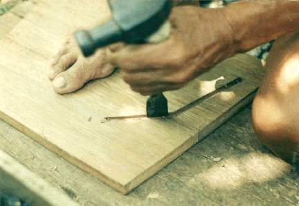
Fig. 4.25 -- Gouge made into base with hammer and chisel for the later insertion of resonator box
4.6.2 Insetting the Resonator Box in the Base
Using the base mortise cut as the central point of reference, the resonator box was aligned. Once the box was centered and in the correct position, an outline was drawn around both exterior and interior edges of the resonator box on the base. This outline was used to as the guide to cut a groove or slot.
To gouge out this outline to a depth of approximately 1 cm (3/8 in), a hammer and various chisels were used. (see Fig. 4.25) Since the tilt of the box, as it insets into the base, did not enter directly at a 90 degree angle, compensation had to be made for the correct angle of the resonator box into the slot. Little by little, adjustments were made until the resonator box finally fit tightly into the groove. The sequential procedure was basically the same as with the base mortise, to place and adjust. Once the groove was cut and adjustments made, glue was applied to contacting edges of the box and the groove and then the two were joined together. A few small metal nails were pounded through the resonator box into the base at various places along the inside edge of the box to make sure the joint was secure. These nails were left in the harp permanently.
4.7 THE FOREPILLAR/tempos or pendulan
Much time went into carving the forepillar, since it shows more aesthetic ornamentation than any other part of the harp. Mr. Abecia was a carpenter by trade and his talents as a furniture maker were used extensively in designing and carving the patterns for the harp's forepillar.
White tugas (similar to teak wood), also called molave in the Visayas, was the wood used for the forepillar. It was chosen by Abecia because of its hardness and strength. The particular piece of tugas for this harp was taken from lumber which came out of a building over 100 years old. It is illegal now in the Philippines to cut fresh tugas without a special forestry permit.
Tugas is a heavy and dense material and would have also been a good wood to use for the harp's neck as well, though the weight of the wood is restrictive to portability.
length of tugas was sawed lengthwise in half, essentially making enough material for two forepillars. A new length was measured, marked and cut to 132 cm (52 in) using a saw. Using the bolo, excess wood was chopped off the sides of the rectangular length until an approximately 4.5 cm (1 3/4 in) width was attained on the four sides. After this, the four sides were planed to a final width of 3.8 cm (1.5 in) square.
4.7.2 Cutting and Squaring the Forepillar
The process of making the forepillar began by bisecting a length of tugas approximately 140 cm (55 in) x 15 cm (6 in) x 10 cm (4 in). After measuring with a ruler, and scoring lines using the marking gauge, the
4.7.3 Rounding the Central Cylindrical Portion
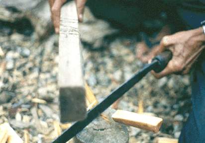
After the planing and squaring of the forepillar length, the next step was to carve the middle portion into a cylindrical shaft while leaving shorter rectangular lengths on opposing ends of the forepillar. The rectangular ends of the forepillar measured 28 cm (11 in) long at the top end which would connect to the neck, and 25 cm (9 3/4 in) long on the bottom end, thus making the center portion 69.5 cm (27 3/8 in) in length when finished.
The rounding procedure began by marking around the four squared edges of the forepillar at both ends using a T-square and a pencil. A saw was then used to make cuts down to a depth approximately 0.1 cm (1/16 in) along those penciled lines. These cuts essentially marked the boundary of cylindrical portion between the two squared ends.
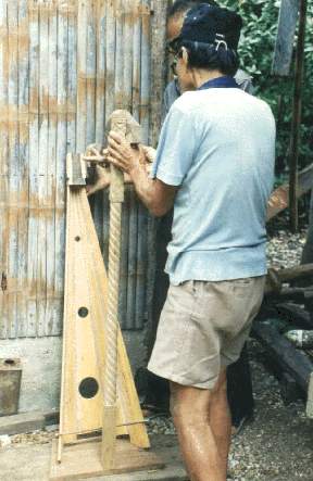
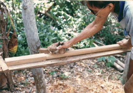
A bolo was used chop off the four prominent edges of the rectangular length between the boundaries in the initial rounding process. (see Fig. 4.26) Once these edges were removed, a more rounded shape began to take form. Different planes were then used to further smooth any pronounced edges until a more cylindrical shape was obtained. (see Fig. 4.27) A tool called a scraper, was used to continue smoothing the surface. (see Fig. 4.28) A chisel was used to finish the areas at the boundaries near the squared edges where the planes or the scraper could not be used.
Fig. 4.27 -- Using plane to smooth rounded middle portion of forepillar
The next step was to carve a spiraling motif onto the cylindrical middle portion of forepillar. This pattern was like a thick twisted rope in appearance. This design, as mentioned before in Chapter 3, was a familiar aesthetic pattern seen on other harps and in furniture made in the Philippines.
4.7.4 Laying Out and Carving the Spiral Pattern
At the boundary points between the round and squared portions of the forepillar, center points were measured and marked on each of the four squared sides next to the boundary. It was from each of these center points that each of four lines would emanate in a continuous spiral. (see Diag. 4.4, 4.5)
Diag. 4.4 -- Points on forepillar where the temporary nails were set
To begin this part of the procedure the first step was to draw the spiral lines onto the cylindrical middle portion. First, a nail was placed into one of the previously marked center points on the upper squared end. A string was attached to that nail and was then wound in a spiral down the center portion and tied to a nail placed at the same central position at the opposite end, on the same facing side. Measurements made using a ruler helped determine equal spacing as the string spiraled down the post. A perfect spiral looks like a series of parallel lines which must be evenly spaced. After time was spent measuring and remeasuring the distances between the parallel lines, a pencil line was marked along the string, used as a guide. This was the first of four spiral outlines made. After drawing this, the centered nails, and the string, were removed. The post was rotated 1/4 turn and nails were inserted at the same corresponding center points on this next side. The same procedure was done on this side as the one before. (see Fig. 4.29) The following two sides were processed in the same way until all four sides of the post had spiral lines drawn from them on to the rounded middle portion of the forepillar, creating a series of four parallel lines.
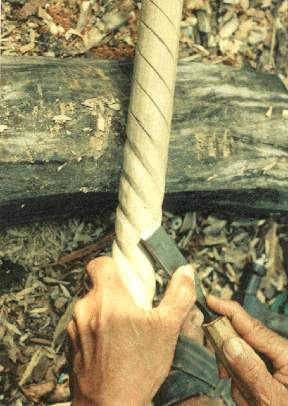
Using the four spiral outlines as guides, a saw was used to cut along each of the lines down to a depth of about 0.1 cm (1/16 in). (see Fig. 4.30) Using these scored lines as borders, chisels and hammer were used to carve a textured surface giving the impression of an embossed twisted strand of rope. The elevated embossed area was located between each of two spiral lines. (see Fig. 4.31) Since there were four lines total there were two complete sets of spiraling strands. To finish, a small chisel, used by hand only, and later, sandpaper, were made to smooth the embossed surface.
Fig. 4.29 -- Measuring distance between lines made with the spiral string guide
Fig. 4.30 -- Cutting along spiral lines with a saw preceding the carving
Fig. 4.31 -- Carving details of spiral rope motif on forepillar middle portion
Diag. 4.5 -- Top of forepillar design to drawn to scale

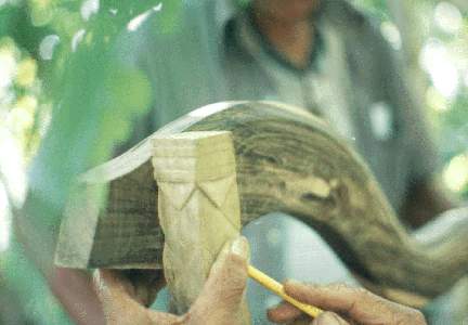
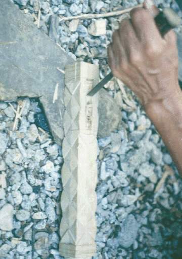
4.7.5 Making the Diamond and Horizontal Cut Patterns
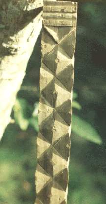
Ornamentation of the top rectangular end was a combination of two basic patterns. Two series of horizontally cut and beveled lines bounded a lengthier embossed diamond pattern between. Both patterns were drawn first with a pencil on the rectangular section of the forepillar using a ruler to make all parts of the design equal in dimension. Since the side of the forepillar facing the neck was to eventually have a mortise cut into it for the neck tenon, that side had only a partial diamond pattern carved on it. (see Diag. 4.5)
After the pattern was measured and drawn, all lines were cut with a saw down to about 0.1 cm (1/16 in) depth. Carving was done with hammer and chisel to define the pattern. Each individual diamond and half-diamond shape was cut to be slightly elevated at the center while the outside edges gave definition and depth to the design. (see Fig. 4.32) This texture was accomplished by using a chisel to make individual cuts which began at the center of the diamond and cut at an angle down toward each exterior edge previously scored with the saw. This carving process was spread over a few days. Abecia alternated his time with other harp-making activities.
The horizontal line motif located on the top and bottom of the diamond pattern were a mixture of beveled cuts or rounded embossments, all cut with chisels. The bottom rectangular end of the forepillar near the base was left plain except for only a few horizontal details, like those described above, made at the bottom boundary of the spiral. (see Diag. 4.5)
Fig. 4.32 -- Detail of forepillar top ornamentation before final finishing
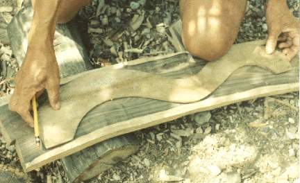
A block of robles lumber, described before, 71 cm (28 in) x 15 cm (6 in) x 5 cm (2 in) was the rough stock for the neck. First, the block had an initial planing on both sides to obtain level surfaces. Then, using a thin plywood template for the purpose, the general shape of the neck was marked on to the lumber, but slightly larger that the template. (see Fig. 4.33) Using this outline, larger chunks of wood were cut out, first, using a saw, then a bolo, to chop out a closer outline from the traced pattern.
Additional planing along the length and width reduced the neck to a more desirable depth of about 4.5 cm (1 3/4 in). Again, the template was used and a closer pencil outline was drawn on the wood before proceeding with the finish carving using, mainly, a hammer and chisel.
The width of the neck was variable, as on most harps. On this harp the neck ranged from a minimum of 5.8 cm (2 1/4 in) to a maximum of 10.2 cm (4 in) wide. The carving process took a few days overall, as Abecia did other jobs on the harp. Even though the neck design itself looked rather simple, it took a number of hours to finish it to its final form.
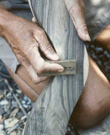
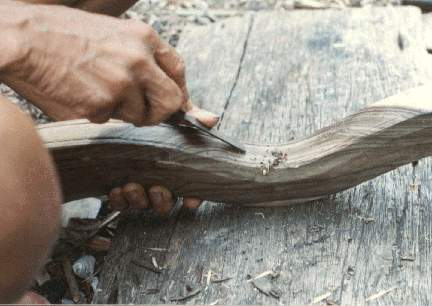
The ornamental carving was done on both sides (width) and the top (depth) of the neck. The motif used on top (depth) of the neck was basically only a pair of parallel lines cut along the curvature at the outer edges along the length. This was done by first using a small marking gauge especially made to get into the tight curves, to score lines at equal distances along the edges. (see Fig. 4.34) These lines were then cut to a depth of about 0.1 cm (1/16 in) using a saw, where possible, and a chisel in other parts where the
Fig. 4.33 -- Template used for neck
Fig. 4.34 -- Special small marking gauge used to score lines on the tight curvature of the neck
saw could not be used. Between the parallel lines an embossed surface was made using the chisel. This elevated the middle area between the parallel lines while leaving the outer edges at a slightly lower depth. (see Fig. 4.35)
The sides of the neck (width) were each made to have a three faceted surface along most of their length. The first, top facet was an approximately 60 degree bevel, 1.3 cm (1/2 in) wide, made from the top (depth) cutting into the side (width) along the curvature of the neck its entire length. (see Fig. 4.36) The small marking gauge was used again to score lines along the curvature at an equal distance. The scored lines were used as the facet boundaries. These lines were cut deeper into the wood with a chisel for better definition.
The second facet kept the initial level surface of the width, but was bounded by scored, mainly, parallel lines, approximately 1 cm (3/8 in) wide, made with the small marking gauge and then a chisel. Between these lines the surface was embossed in a similar way to the top (depth) surface of the neck. At the opposite ends of the parallel lines of the second facet, near theforepillar and near the foundation block, the lines were made to flair out. The third and last facet extended from the bottom line of the second facet, cutting inward at a steep angle, approximately 75 to 80 degrees, to the lower end of the neck's width. (see Fig. 4.37) Since the neck itself is not a consistent width the entire length of the last facet was a variable dimension from 3.2 cm (1 1/4 in) to 6 cm (2 3/8 in) wide. This third facet was both functional as well as ornamental because it allowed the strings to stay a distance away from the neck so to vibrate freely.
Fig. 4.35 -- Carving the slight embossment on the neck's top depth with a chisel
Fig. 4.36 -- Carving the first angular facet between the top depth and side width with a chisel
Fig. 4.37 -- Initial carving of the bottom facet on the side width of the neck
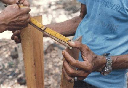
Fig. 4.38 -- Layout to determine length of neck and shoulder of tenon
4.8.1 Laying Out and Cutting the Neck Tenons
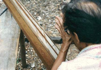
Two tenons (male end of joint) were cut for the neck, one to fit into the forepillar mortise (female joint) and the other to fit into the mortise made in the foundation block.
With the resonator box and the forepillar tenon set into the base mortises, a preliminary neck length was measured between the forepillar and the foundation block of the resonator box. Care was taken to make sure the post was at a 90 degrees angle to the base when making the measurements. During this process measurements were made for the neck/forepillar tenon. This was done by laying the neck along the side of the forepillar and the box and drawing a line across the neck using the forepillar as the straight edge. (see Fig. 4.38) The mark made on the neck would be the tenon's shoulder that would fit flush with the forepillar. Tenon parts and dimensions are shown in Diag. 4.6.
The tenon depth, width, and length were marked using a marking gauge and pencil and were then cut using a saw, hammer and chisel. (see Fig. 4.39) Using the outline of the neck tenon as a template, the outline for the forepillar mortise was traced. The procedure for cutting the mortise and obtaining a correct fit was basically the same sequential process as cutting the mortise into the base. (see Fig. 4.40) Once the forepillar/neck joint was fit correctly, the neck tenon was made for the neck/resonator box joint at the rear of the harp. (see Fig. 4.41)
The rear neck tenon was made in a similar fashion to the previous one. The forepillar was inserted into the base and the neck inserted into the
Fig. 4.39 -- View of front of neck tenon for the neck forepillar joint
Fig. 4.40 -- Cutting of forepillar mortise for the neck/forepillar joint
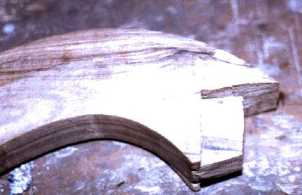
Fig. 4.41 -- View of rear neck tenon for the neck/foundation block joint
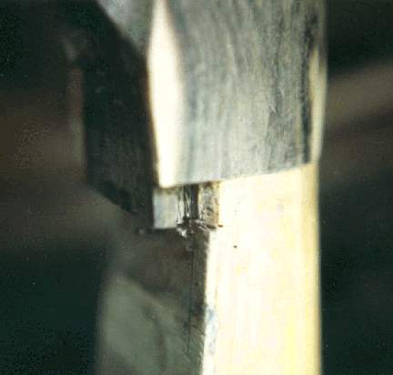
forepillar mortise. With the forepillar standing at a 90 degree angle to the base, the rear of the neck was marked using the foundation block as a guide. This inverted L-shaped outline would basically mark the shoulder of the neck tenon. (see Diag. 4.6, Fig. 3.10) This tenon was more complex and the marking and readjusting of the fit was based more on experience than
simple method. Unscaled drawings show the basic dimensions and configuration of both neck tenons in Diag 4.6, and the forepillar mortise and the foundation block mortise in Diags. 4.7 and 4.8.
Using the outline of the neck/block tenon as a template, the mortise on the foundation block face was traced and cut. The adjustment process was more complex than with the other mortises, but basically followed the same sequential pattern of cutting, placing together, removing, making adjustments with the chisels, and so forth.
Once all the structural units were completed, the various pieces were assembled. The resonator box and the forepillar connected to the base, and the neck tenons were placed in the foundation block and the forepillar mortises. No nails were used for the joints except on the resonator box inset into the base.
This assembly process involved applying glue to all contact points and then pounding the components tightly together with gentle force. To keep the joints tight while the glue dried, a rope was used to draw the structures of the harp together. The rope was attached to the base, strung up around and tied to the middle of the neck and also tied around the forepillar and the resonator box toward the middle of the harp. To tighten the ropes and, thus, the joints, sticks were placed between the span of the rope and twisted, drawing the pieces together tighter and tighter, until the glue began
Diag. 4.6-- Dimensions of the neck tenons, front and rear
NECK TENON OF FOREPILLAR/ NECK JOINT
NECK/BOX TENON
 SIDE VIEW
Diag. 4.7--Forepillar mortise of the neck/forepillar joint
Diag. 4.8 Foundation block mortise of neck/block joint
to squeeze out of the joints. The harp was allowed to dry with the ropes on for two days before the soundboard layout was begun.
4.8.2 Peg Hole Placement and Drilling
The string holes marked on the soundboard centerstrip were used to find the location of the peg holes in the neck. These had to be aligned so that all the strings would be approximately parallel to the forepillar. The curvature of the neck required that the placement of some peg holes be closer and some farther apart. Because of this, the peg holes could not be spaced exactly the same distance between each of the the peg hole centers. This caused some trouble with the peg hole layout.
Abecia laid out the peg holes by stretching ordinary string between temporary nails placed in the string hole points on the soundboard centerstrip and corresponding nails on the neck. Each peg hole had its own temporary nail marking each place to drill. This method of peg hole location, using string, was done to visualize how the harp strings would align in parallel and how even the gap would be between the strings. This process had to be redone two times because toward the end of the process, the strings would no longer be parallel to the forepillar.
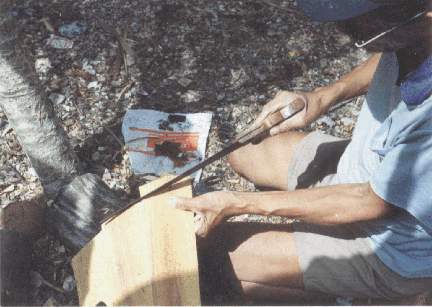
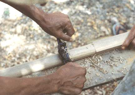
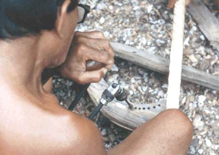
A brace and a 1/4 inch (0.5 cm) drill bit were used to bore the peg holes. Because of the thickness (depth) of the neck it was necessary that the holes be drilled on both sides of each hole to make sure the bore was centered correctly on either side. (see Fig. 4.42)
Fig. 4.42 -- Brace and bit is used to bore tuning peg hole into the neck
The tuning pegs (or pins), called liso in Bisayan were made of sibucao. Sibucao [Caesalpina] is also called sappan and similar to Brazil wood. This is a small tree, approximately 3-4 inches in diameter and 10-15 feet tall, used locally for tool handles. The wood is best worked when totally dry, but can be cut into pieces when green and dried, to make pegs. Sibucao was a popular dye-wood to the Chinese, exported from the Philippines in great quantities during the nineteenth century. The heartwood produces a dark red-orange color dye. (Sherfesse 1916:118) Sibucao wood was the most common material used for Filipino harp tuning pegs.
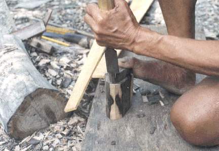
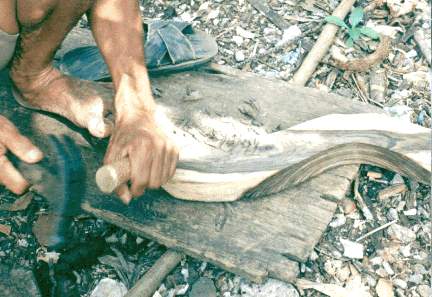
To make the pegs, a log of 7.6 cm (3 in) diameter, cut approximately 10.2 cm (4 in) in length, was initial source material for splitting into pegs. The short piece of log was split going with the grain, first in half, then quarters, eighths, and sixteenths and eventually further into pieces nearing the size of a harp peg. (see Fig. 4.43) For the final process of whittling the pegs, each small piece of wood was finally split down to a rectangular piece, the dimensions approximately 9 cm (3 1/2 in) x 1.5 (7/16 in) cm x 1 (3/8 in) cm.
This rectangular piece of wood was then whittled down, using a bolo, until the shape and diameter matched a model peg. Each peg was rounded to a diameter fitting the peg hole ~ 0.6 cm (1/4 in) diameter on one end and left fairly rectangular on the other (actually more of a trapezoid). The rounded part of the peg was also made to be slightly conical as it met the rectangular part. (see Fig. 4.44) Each had to be inserted into one of the drilled holes in the neck and had to go through a gradual process of adjustment until each peg fit correctly into its own specific hole. Pegs were then numbered so that each peg could be placed in the right hole if they came out and were scattered about. With all the pegs fitted, the ends of all the pegs on each side of the neck were marked and cut to give an even appearance. Each peg was then taken out and a small hole was drilled at the tip of the rounded end with an awl to allow for the placement of the nylon strings.
A templador was also made. This was from the same peg wood material, but was left rectangular. On one end of the templador a rectangular cut was made to fit the squared part of the peg. Nylon twine was wound around the cut end for reinforcement. (see Fig. 4.45)
4.9 FILLING GAPS WITH SAWDUST AND GLUE MIXTURE
Abecia made a mixture of available sawdust and weldwood, a type of dry glue to which water is added. With this mixture he would fill in any gaps or places he though might need some strengthening, such as the inside of the resonator box along stave joints or at the bottom of the soundboard at the base, and several other places.
Fig. 4.43 -- Gabing using the bolo to cut wood pieces to size for tuning pegs
Fig. 4.44 -- Bolo is used to shape tuning peg to fit
Only one thick coat of varnish was applied after the harp was finished and lightly sanded. Abecia liked to use an orange varnish which he mixed with some thinner.
Once the varnish dried, the nylon harp strings were attached to the pegs and the soundboard. This ended the harp making process, that took nearly a month, excluding Sundays and fiesta days.
Features that distinguish this harp in the realm of the Bisayan genre are 1) its size, compared to Ilocano harps this harp is smaller; 2) the use of wood pegs without string guides is a characteristic of most Bisayan harp and no Ilocano harps; 3) the use of a variety of different woods in its makeup is more common to Bisayan harps. Since the harp resonator is staved and not hollowed from a log it does not fit into the structural majority of Bisayan harps.